
How To Choose An Earthing Switch Operating Controller?
What Does an Earthing Switch Operating Controller Do?
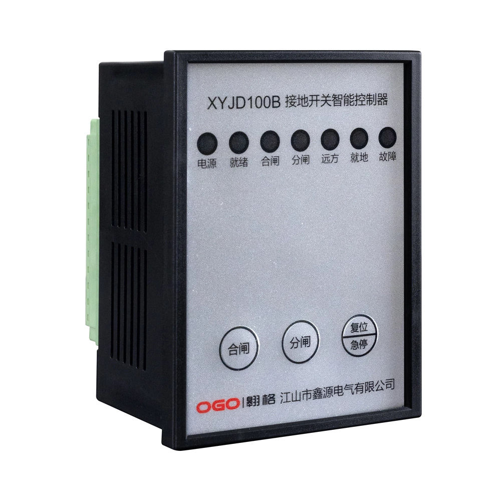
An Earthing Switch Operating Controller manages the operating process of an earthing switch. It connects control commands with the switching mechanism. The controller can coordinate electrical signals, mechanical movement, and position feedback. Its design depends on the switchgear structure and operating method. Some systems use local control, while others support remote commands. Interlocking functions can also prevent unsafe switching sequences. The controller must therefore match both the switch mechanism and control circuit. Engineers should check its input signals, output contacts, and operating interface. Mechanical travel also requires careful verification before installation. Correct matching helps maintain reliable switching performance during routine operation. It can also simplify status monitoring during maintenance and inspection activities.
Which Switchgear Conditions Should the Controller Support?
Switchgear normally contains several components that must operate in a defined sequence. These components may include circuit breakers, disconnectors, earthing switches, and cabinet doors. Their positions can determine whether another operation becomes permissible. For example, an earthing switch should not close under prohibited electrical conditions. The control system may receive position signals from auxiliary contacts. It can then process these signals before allowing an operating command. Engineers should identify every relevant equipment state before selecting a controller. The required logic should also reflect the actual switchgear circuit. Complex installations may require several interlocking conditions. A clear control sequence reduces operating errors and improves coordination between electrical and mechanical functions. This approach also supports safer maintenance procedures.
How Does Rated Voltage Affect Controller Selection?
Rated voltage affects the insulation environment surrounding the switchgear. However, the switchgear voltage does not always equal the controller’s control voltage. A medium-voltage cabinet may use a separate low-voltage control circuit. Engineers should therefore check both values independently. Control power can commonly involve AC or DC supplies. The Earthing Switch Operating Controller must support the specified voltage range without unstable operation. Insulation distance also matters when the controller operates inside a high-voltage cabinet. Terminal spacing, enclosure design, and wiring arrangement can affect electrical safety. Temperature changes may further influence component performance. Buyers should request complete electrical specifications from the supplier. These specifications should identify control voltage, contact ratings, insulation requirements, and operating limits. Such information provides a clearer basis for technical compatibility.
What Operating Mechanism Should You Consider?
The operating mechanism determines how electrical commands become mechanical movement. A motorized system may use a motor, gearbox, transmission shaft, and limit switches. Each component affects torque, travel, speed, and operating reliability. Some mechanisms require a defined rotational angle for complete switching. Others may use linear movement through a mechanical linkage. Engineers should confirm the required operating torque before choosing the controller. Insufficient torque can prevent complete movement or create unstable operation. Excessive torque can stress gears, shafts, and connected switch components. Limit switches should also correspond with the actual end positions. Mechanical interfaces require equal attention during selection. Mounting holes, shaft dimensions, rotation direction, and operating travel should all match the switchgear design. Early verification can prevent costly modification after delivery.
How Important Is Interlocking Logic?
Interlocking logic controls whether specific switching actions remain permissible. Electrical interlocking can use auxiliary contacts, relays, sensors, and control circuits. Mechanical interlocking can physically restrict movement under certain conditions. Many switchgear systems combine both approaches for additional protection. A typical sequence may require a circuit breaker to open first. The disconnector may then reach its required position. Only after those conditions can the earthing switch receive an operating command. The exact sequence depends on the equipment design. Engineers should map every permitted and prohibited state before finalizing the control circuit. Remote commands should follow the same safety logic as local commands. Clear state definitions also simplify troubleshooting. Suppliers should receive the complete interlocking requirements before producing customized control equipment.
What Position Feedback Should Be Included?
Position feedback confirms the actual state of the switching mechanism. Common signals include open position, closed position, and intermediate status. Auxiliary contacts often provide these signals to the control system. Limit switches can also identify the mechanical end positions. Accurate feedback matters because a command does not always prove completed movement. A motor may receive power while the mechanism remains incomplete. The controller should therefore verify the final position whenever the system design requires it. Remote monitoring systems can display these signals to operators. Engineers should confirm contact type, contact rating, signal voltage, and terminal arrangement. They should also check whether the feedback remains stable during vibration or repeated operation. Reliable position feedback supports accurate status confirmation and improves maintenance efficiency.
Which Control and Installation Details Matter?
Installation details can affect both operating reliability and maintenance access. The control voltage should match the available auxiliary power supply. Terminal capacity should also support the required signal and control wiring. Cabinet space determines whether technicians can install and service the controller easily. Mechanical orientation can influence cable routing and transmission alignment. Engineers should verify mounting dimensions before shipment. Shaft connections require accurate alignment to avoid excessive mechanical resistance. Wiring terminals should have clear identification and suitable connection methods. Buyers should confirm these points before placing an order:
- Control voltage and electrical contact ratings
- Operating torque, travel, and rotation direction
- Mechanical mounting dimensions and shaft interface
- Interlocking conditions and required signal inputs
- Open, closed, and intermediate position feedback
- Environmental temperature and humidity limits
- Wiring diagrams, inspection records, and technical documents
These details form a practical specification for supplier communication.
How Do Installation Conditions Affect Long-Term Operation?
Switchgear environments can expose control components to heat, humidity, dust, and vibration. Internal cabinet temperature may rise because of nearby electrical equipment. High humidity can increase condensation risks during temperature changes. Dust can accumulate around mechanical interfaces and ventilation openings. Engineers should therefore check the controller’s environmental operating range. Materials should also suit the expected cabinet conditions. Terminal protection becomes important when moisture or contamination may occur. Mechanical components require suitable durability when repeated operations are expected. Installation space should provide sufficient clearance for wiring and maintenance. Cable routing should avoid unnecessary mechanical stress on terminals. A suitable enclosure and mounting arrangement can support stable operation over time. Environmental requirements should form part of the initial technical specification rather than an afterthought.
What Testing Should You Request From a Supplier?
Testing should verify both individual functions and relevant operating characteristics. Functional testing can confirm command response and correct switching sequences. Position testing should verify accurate open and closed feedback. Repeated operation can reveal problems with motors, gears, switches, or mechanical alignment. Electrical tests can check insulation performance and contact continuity. Suppliers should also verify terminal connections against approved wiring diagrams. Factory inspection records can provide evidence of completed checks. Customized equipment may require additional tests based on the switchgear application. Engineers should define acceptance criteria before production begins. This approach creates measurable requirements for inspection and delivery. Testing records should identify tested items, results, and applicable technical specifications. Complete documentation can also simplify future commissioning and maintenance activities.
How Can Supplier Documentation Reduce Selection Risks?
Technical documents provide essential information for installation and verification. A complete specification should identify electrical ratings, mechanical dimensions, and operating conditions. Installation drawings can confirm mounting points and transmission interfaces. Wiring diagrams show control terminals, feedback contacts, and signal relationships. Product drawings can also reveal clearance requirements inside the cabinet. For customized projects, suppliers may provide drawings for approval before production. Buyers should compare these drawings with the actual switchgear design. Any mismatch should be resolved before manufacturing begins. Inspection reports can further support incoming quality checks. OEM and ODM projects require especially clear communication because interfaces may differ between applications. Complete documentation reduces ambiguity between engineering, purchasing, installation, and maintenance teams. It also provides useful records for future replacement or system modification.
Why Should the Controller Match the Complete Switchgear System?
A controller cannot be selected only by checking one electrical rating. Its performance depends on the complete mechanical and electrical system. The operating mechanism determines movement requirements and torque demand. The control circuit determines voltage, signals, and permitted commands. The interlocking design determines which states can trigger specific operations. Position feedback confirms whether the expected mechanical state has actually occurred. Cabinet dimensions determine installation feasibility and maintenance access. These factors must work together without conflicting requirements. New switchgear projects usually allow more flexibility during initial design. Retrofit projects often require closer attention to existing dimensions and wiring. Engineers should therefore evaluate the Earthing Switch Operating Controller as part of the complete switching system. System-level matching can reduce installation changes and commissioning problems.
What Questions Should You Ask Before Ordering?
A structured technical discussion can prevent misunderstandings before production starts. Buyers should provide the supplier with switchgear drawings when customization may affect mechanical interfaces. Control voltage and signal requirements should receive clear confirmation. The required operating sequence should also appear in the technical specification. Position feedback should identify every required state and contact arrangement. Environmental conditions should include expected temperature, humidity, and installation location. Testing requirements should define inspection items and acceptance criteria. Buyers should also confirm delivery documents and replacement support. For customized projects, approval drawings can provide another verification stage. The Earthing Switch Operating Controller requirements should create a common technical reference for both parties. They also help purchasing teams compare proposals using consistent engineering criteria. A detailed specification usually makes later installation and commissioning more predictable.
How Can an Earthing Switch Operating Controller Support Safer Operation?
Safe operation depends on coordinated control, accurate feedback, and appropriate interlocking. The controller should respond only to valid operating conditions defined by the switchgear design. Position signals should provide reliable confirmation after each required movement. Interlocking functions should prevent prohibited sequences through electrical or mechanical means. Local and remote commands should follow the same operating logic when both are available. Engineers should also verify emergency procedures and manual operating provisions. Maintenance personnel need clear information about equipment states before intervention. Supplier documentation should describe terminals, signals, operating limits, and inspection requirements. Regular functional checks can identify worn contacts or mechanical problems. Proper commissioning should verify the complete sequence rather than testing isolated components only. These practices support dependable operation throughout the equipment service period.
FAQ
Can an Earthing Switch Operating Controller Be Customized?
Customization can cover electrical, mechanical, and control requirements. Suppliers may adjust control voltage, terminal arrangements, mounting dimensions, and shaft interfaces. Feedback contacts can also be configured according to the switchgear control circuit. Some projects require special interlocking sequences or additional signal outputs. Engineers should provide accurate drawings and technical specifications before production. Clear requirements help suppliers confirm whether the requested configuration is practical. Prototype testing may also help verify mechanical movement and electrical signals. For larger projects, approval drawings can provide an additional verification stage. Buyers should confirm all customized parameters before mass production. This process reduces the risk of mismatched interfaces during installation and commissioning.
What Signals Does an Earthing Switch Controller Usually Use?
Typical signals include open position, closed position, and intermediate status. Auxiliary contacts or limit switches commonly generate these signals. The control circuit may also receive permissive signals from other switchgear components. Circuit breaker status, disconnector position, and door status can affect operating permissions. Voltage presence information may also participate in certain control schemes. Signal types depend on the switchgear design and control architecture. Engineers should confirm contact type, voltage rating, current rating, and terminal assignment. Remote monitoring systems may require additional status outputs. Clear signal definitions help prevent incorrect wiring and misleading equipment status. Every required signal should appear in the approved wiring diagram before production.
How Should an Earthing Switch Controller Be Tested?
Testing should cover electrical functions, mechanical movement, feedback signals, and interlocking logic. Functional tests should confirm that commands produce the intended operating response. Mechanical tests should verify complete travel and correct end positions. Feedback tests should confirm accurate open and closed indications. Repeated operation can help reveal mechanical resistance or unreliable limit switches. Electrical inspections may include insulation and contact continuity checks. Customized controllers may require additional tests based on the application. Factory records should document tested functions and measured results. Commissioning should then verify the controller together with the complete switchgear system. System testing is important because individual component performance cannot confirm correct overall sequencing. Acceptance criteria should be agreed before delivery.